English
imagelib
Thumbnail
product
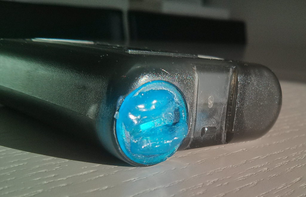
ADHESIVE WELDING
categories
Consumer adhesives
Contact us


http://www.afinitica.com
mail:info.bell@bostik.com
Postal Address:
Edifici Eureka. Campus UAB.
08193 Bellaterra
Barcelona - Spain
Phone number +34 931 431 952
skype: afinitica
